Design summary
Frame construction is planned to be made of aluminium profiles, each parts riveted together. Shell – lifting gas container is 800g sounding balloon.
With hull length and main diameter
gives fineness ratio
.

Shell membrane stress
Calculation is based on Laplace equation for thin membrane
describing two-dimensional membrane stress with rotational symmetry.
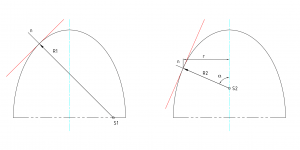
First main radius is given and second main radius
can be written as
For given can be solved angle of tangential tension
as
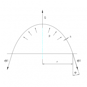
static equilibrium on shell element
where axial force on shell section is
after modifying can be written axial tension

substitution back to Laplace eq. will give second tangent tension
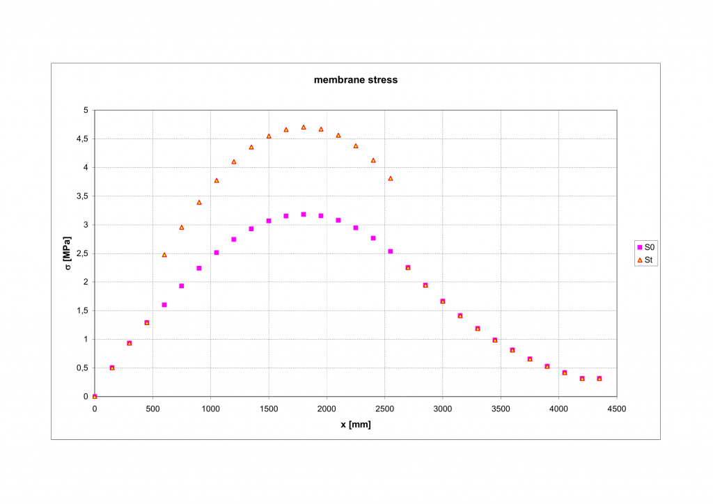
Shell inflating
Graphs computed for inflation of sphere , variables are functions of relative membrane deformation
Internal pressure function described with equations @ http://journals.sagepub.com/doi/abs/10.1177/108128650200700506
balloon parameters: 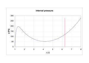 weight 800g
uninflated dia
burst dia
membrane initial thickness
critical deformation
membrane thickness depends on deformation by equation
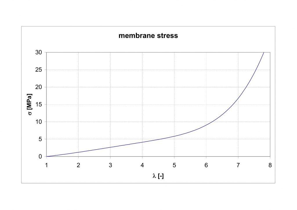

Function of membrane stress and thickness is based on Yeoh model computed by http://www.lajss.org/index.php/LAJSS/article/view/2622
On the basis of experimental test data of sounding balloon manufacturer – https://novalynx.com/store/pc/400-8200-Series-Weather-Balloons-p882.htm , can be determined, that membrane burst with stress load for critical deformation
. Computed maximal stress of shell is
and therefore the membrane load stays in safety area with save coefficient
.
Buoyancy
constants:
air density NTP – normal temperature and pressure defined as 20oC and 1 atm
hydrogen density NTP
shell volume
therefore buoyancy force is
for fully inflated shell is gross lift force
For designed total weight of airship , gives free lift of
. To obtain vertical force stability, it is needed to adjust up to weight equal to gross lift by the ballast. Ballast is situated in front section of gondola. Weight of ballast will be adjusted in dependency of real airship weight and weather condition (atmospheric pressure and ambient temperature). To adjust position of center of gravity towards to the same vertical line with buoyancy center, which is indispensable for horizontal flight stability, gondola is movable mounted on bottom beam, so the position of COG can be changed with position of gondola.
Fluid dynamics
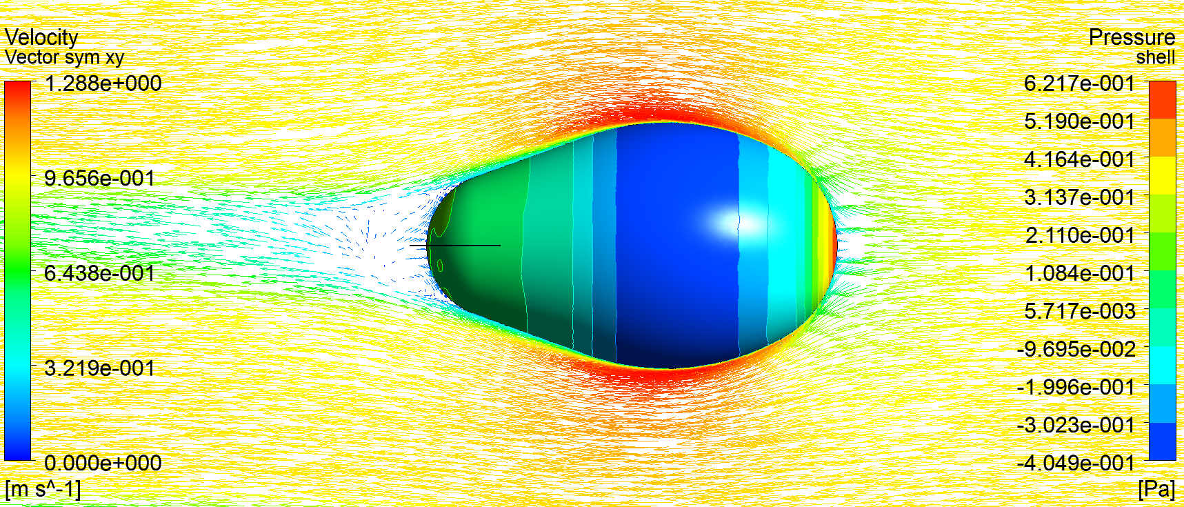
static flow field over shell geometry
analysis has been solved for travel speed
Reynolds number , for
main diameter , kinematic viscosity of air
is
computed shell drag force
Results for variable travel speed could be obtained with drag coefficient making use of equation
which gives for defined geometry .
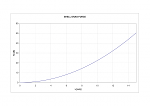
With computed characteristic of dependency shell drag force and travel speed, could be determined the motors thrust force which must be .
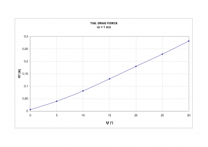
With the same method, tail drag force is computed. Function of rudder acting angle and tail drag force
is almost linear.
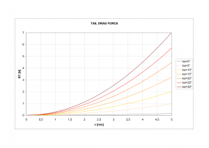
Applying the same formula for drag coefficient, it is computed the exponential characteristic for several rudder angles increasing with square of velocity.
Stability
In horizontal direct flight, center of buoyancy and center of gravity must lie on the same vertical line. This condition is achieved with ballast position adjustment during pre-flight preparation.
On figure, airship drawn in inclined flight, acting forces are shown below.
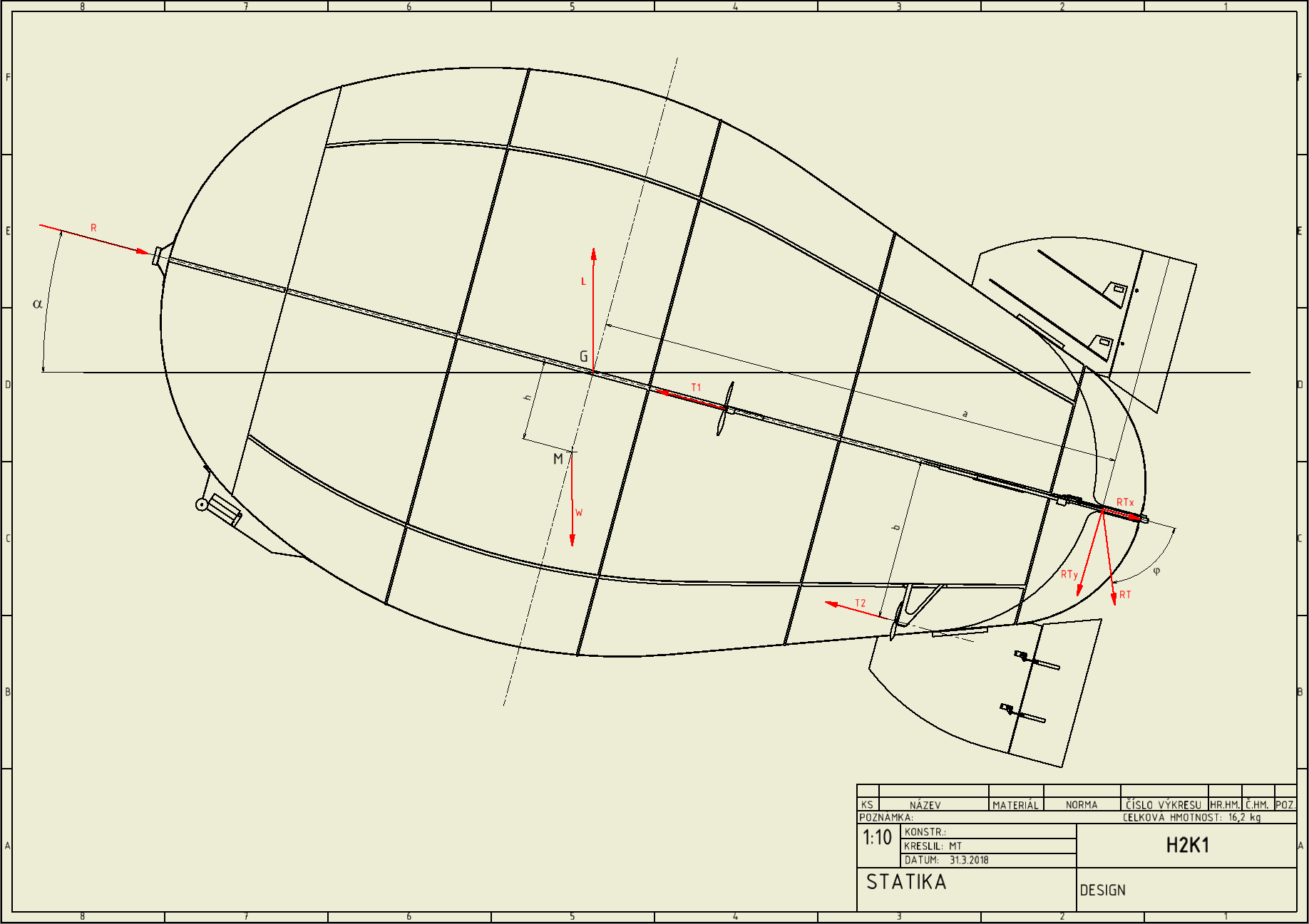
For condition of static equilibrium, can be written for moment about G
Airship thrust engines are designed in four units acting in two parallel couples. Resultant force lies on hull center line and acting directly against drag force
. The second one
acting in distance
bellow the hull centerline.
During the horizontal flight, most thrust power will be generated with ,
will be used as compensator or in cooperation with rudder for increasing a total thrust. For inclined flight (particularly during the start), most thrust will be supplied by
engines to have additional positive moment about COG. This should leads the airship to elevate a nose.
In case of airship ascent or descent, direction of motion is not symmetrical with hull centre line, but it seize an angle between these two lines. This effect causes asymmetrical pressure distribution over the shell and creates additional dynamic force. For an example of nose elevated airship moving forward, due the increased pressure below the hull, center of pressure over the shell lies down the hull center line and causes force acting in positive direction of rotation, adding the positive moment about COG, so this force trends to elevating the nose up. This force, called dynamic lift of hull, is hard to determined numerically because the direction of motion angle is not easily predictable in decency of hull center line angle. In airship design is described with empirical formula based on real model measurements. For this design purpose, this force is omitted and it is assumed that hull centerline angle and direction of motion is the same. Therefore pressure distribution is symmetrical over the shell and resultant drag force lies directly on center line.
Calculation example for inclined flight:
traveling speed
thrust ;
rudder setup
From fluid dynamic analysis can be determined shell drag force and tail drag force
,
.
For unknown center line angle , value can be expressed from static equilibrium as
which is solved for given inputs .
Control
Pitching and yawing rudders have got the same geometry. Kinematic of control mechanism is designed to have the same maximal angle to positive as well to negative rudder deviation. Therefore the controlling has got symmetrical behaviour to both direction. For each rudder, two of parallel acting servo drives is designed so each servo balances a half of force on rudder surface.
Kinematic of control mechanism is described bellow.
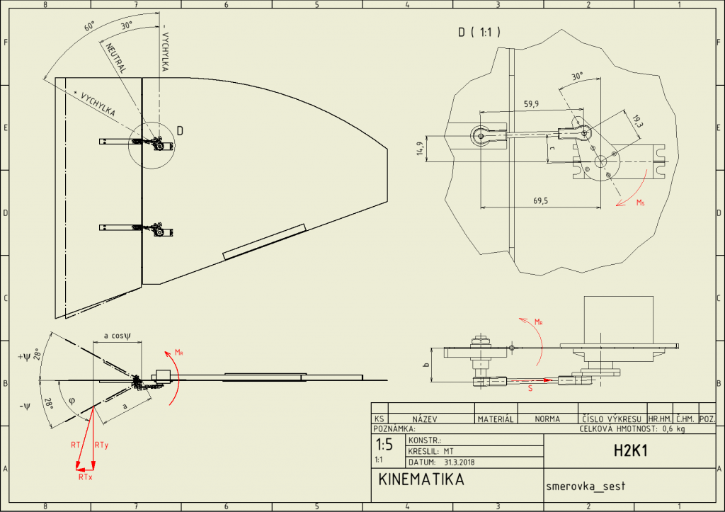
For moment about the axis of rudder rotation can be written static equilibrium
From this equation, force on control rod can be expressed and with substitution to equation for moment about servo axis, moment on servo shaft can be written as
Calculation example of servo moment:
traveling speed
rudder setup
From fluid dynamic analysis can be determined tail drag force , which gives
for one servo;
.
distance and
is for each maximal deviation
For given inputs, moment on servo shaft is
For chosen servo type, maximal torque is .Based on this calculations, the servo drives are able to operate with fully deviated rudders up to travel speed
safely.
Engines
Propeller type had been chosen on basic of required parameters. Calculation of propeller’s static thrust had been done with program at website: https://rcplanes.online/calc_thrust.htm
With 11.1V battery and engine with 1050 RMP/V, propeller static RMP is 11655 rev/min. For chosen propeller type APC SP 10×3.8, it is computed estimated static thrust as 2.318kg.
Assumed for horizontal flight with full thrust of , it gives
.
With comparison of shell drag force characteristic, for full thrust of upper engines, theoretical travel speed is approx. .
Motor maximal peak current gives motor input power
.
Design conclusion
Airship is designed for safety operation up to nominal travel speed . Anyway based on calculations, it is assumed that airship maximal speed should reach approx.
.
With shell volume and gross lift force
and with total weight
, remains
for free lift, which should be enough for omitted parts weights (RC accessories, rivets, electronics,…)
Most of useful information about airship aerodynamic had been drawn in publication of US WAR DEPARTMENT technical manual of 1941, which can be found at the link https://www.faa.gov/regulations_policies/handbooks_manuals/aviation/media/airship_aerodynamics.pdf.
With next step, working drawing will be processed in detail, and realization will continue.




Comments
rigid RC airship \ project H2 — No Comments